Transformers
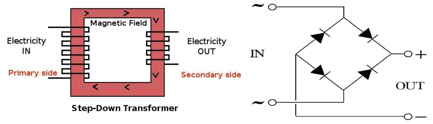
A basic transformer consists of two windings of insulated wires wound around a common iron core.
The power source or supply is hooked to the primary winding, and the load to be served is connected to the secondary winding. When the primary winding is energized an electromagnetic field builds up and then collapses in the iron core, this field cuts through the secondary coil winding inducing power to the load hooked to the secondary.
To understand the transformer easily, keep in mind that the input power should be equal to the output power.
P primary = P secondary then Vp X Ip = Vs X Is
then Vp / Vs = Is /Ip.
In an ideal transformer, the induced voltage in the secondary winding (Vs) is in proportion to the primary voltage (Vp). It is given by the ratio of the number of turns in the secondary (Ns) to the number of turns in the primary (Np) as follows:
Vp / Vs = Np / Ns = Is / Ip
By appropriate selection of the ratio of turns, a transformer thus allows an alternating current (AC) voltage to be “stepped up” by making Ns greater than Np, or “stepped down” by making Ns less than Np.

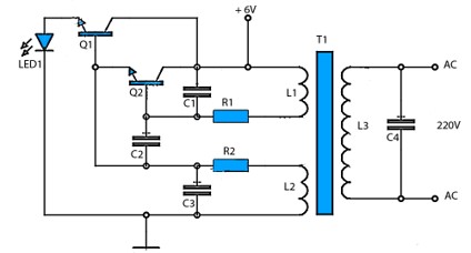
the most common use for a step-up transformer is in an inverter. This takes a direct current and using switching methods (commonly an astable multivibrator) turns it into an alternating current which is fed to the primary of the transformer.